Moog D661-4594C, Eight Months Old: A Wide Loop That Still Centers Itself
Moog D661-4594C, Eight Months Old: A Wide Loop That Still Centers Itself
Most sweeps tell one story. This one tells two, and they sit next to each other in the same results column: hysteresis 10.55 %, starred — the widest loop our D661 shelf has printed — beside a null offset of −0.41 %, which is as centred as this software prints. Those two numbers usually move together. On this valve they moved apart, and the whole record is about reading that split honestly.
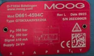
The unit is a Moog D661-4594C, type G75KXAA5VSX2HA, revision L, nameplate date 09/23, serial 2023390626. The test stamp reads 24-05-24 at 11:02, which puts the valve at roughly eight months old when it was swept — young stock, barely past break-in. Rated conditions for the computation were 7.00 MPa and 10.00 V.
What the plate says

Read from our own photograph of the valve before anything was energized:
|
Field |
Value |
|---|---|
|
Manufacturer |
MOOG, D-71034 Böblingen |
|
Model |
|
|
Type |
G75KXAA5VSX2HA |
|
Serial |
2023390626 |
|
Revision / date |
Rev L, 09/23 |
|
Pp |
350 bar |
|
Px |
350 bar |
|
Signal |
±10 mA |
|
Supply |
24 V DC |
The serial prefix 2023 agrees with the 09/23 date field — a small check we run on every unit, because on used stock a serial and a date that contradict each other is the first sign a plate has been moved. These agree. Two details worth noting for readers cross-referencing our archive: the pilot supply rating Px equals the main rating Pp at 350 bar on this plate, and the signal field reads ±10 mA even though the bench command channel that day was a voltage channel. Both are normal for this family; the second one is explained in the next section rather than papered over. The CE mark, the DataMatrix code and the port row X T A P B T1 Y are all intact in the photograph.
The sweep
The static tester was set to a triangular command, amplitude 8 on the voltage scale, frequency 0.05 Hz, offset left blank, output channel 1. Control signal on channel (1) V1, flow signal on channel (4) Q1; coils in series, coefficient 1, test step “all”; the flow basic-characteristic band for the computation was 10–90 %. One full cycle at 0.05 Hz is twenty seconds; the recording runs about twenty-nine, settle time included.
On the unit question: the plate rates the valve’s signal at ±10 mA, while the tester’s command block prints its amplitude in volts on V1. A command stage sits between the software and the coil, and each screen was read in the unit it displayed. We are not converting one into the other, because the conversion belongs to the bench, not to this article.
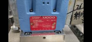
The bench panel during the sweep carries three BLD precision pressure gauges, 0–40 MPa, watching P, A and B, each with its digital indicator below; the feedback-signal, flowmeter and temperature displays sit in the middle band and the ±15 V / ±24 V supply terminals to the right. Nothing on that panel disagreed with the software that day.
The curve itself is where this record earns its keep. Both legs climb to about 100 L/min and flatten inside the 8 V command window — the saturation voltages, 7.31 V and 7.91 V, sit below the rail, so neither leg was clipped by the command edge. That is a stronger position than some records in our archive, where a leg was still climbing when the window closed. Here the flows rest on fully developed curves. The separation between the up-trace and the down-trace — the loop — is wide, and it is the single loudest thing on the screen.

The numbers, as printed
|
Parameter |
+ direction |
− direction |
|---|---|---|
|
Rated flow (L/min) |
101.22 |
99.96 |
|
Saturation flow (L/min) |
100.11 |
99.95 |
|
Saturation voltage (V) |
7.31 * |
7.91 * |
|
Gain (L/min per V) |
15.63 * |
14.70 * |
|
Linearity (%) |
5.66 |
7.04 |
|
Hysteresis |
10.55 % * |
|
|
Null offset |
−0.41 % |
|
|
Symmetry |
5.95 % |
|
The stars are the software’s own marking, kept exactly where it put them; we do not know which limit table it checked that morning. The pattern is worth spelling out: stars on both saturation voltages, both gains and the hysteresis; nothing on the flows, the linearity pair, the null offset or the symmetry.
One arithmetic check, because symmetry is the figure readers most often miscompute. The gap between the two printed gains is 0.93; against the higher leg, 0.93 / 15.63 = 5.95 %, exactly the printed symmetry. Against the mean of the two gains it would read 6.13 %. So this software, like the one on our D661-4041 record, reports symmetry against the higher leg, and we quote its convention rather than inventing a second number.
Eight months old, and the loop is already wide
Hysteresis and null offset measure different failures. Hysteresis is trace separation — how far the down-sweep sits from the up-sweep at the same command — and it is a friction memory: something in the spool, the pilot or the metering edges resists reversal. Null offset is centreing: where zero flow actually falls against zero command. A valve can fail either one alone.
This valve failed the first and passed the second. The −0.41 % offset says the spool comes home; the 5.95 % symmetry says both legs deliver their flow at matching rates once they are moving. What the 10.55 % loop says is that the spool fights on the way, in both directions, every cycle. On eight-month-old stock that shape points at contamination or a friction signature in the pilot stage rather than at wear or a shifted null — but a static sweep alone cannot separate those, and we will not pretend otherwise. The follow-ups we would run are a flush and a re-sweep, and an inspection of the pilot filter; neither was done that morning, so this record stands as-found, and it says so.
The contrast cases in our own archive make the shape easier to see. Our D661-4041 record from the same bench shows the mirror image: a narrow 1.46 % hysteresis loop beside a starred −14.72 % null offset and 25.68 % symmetry — a valve that slides freely but no longer centres. And a fourteen-month-old D633-525B at 0.10 % hysteresis marks the clean end of the same scale. Three records, three shapes, one bench: that is the comparison we wish we had when we started grading used servo valves.
Two comparability notes. This sweep ran at 7.00 MPa, the same rated pressure as the D661-4041 record, so those two tables can be read side by side; the D633 record ran at 17.5 MPa and its flows are not directly comparable to this one. And the stamp on this record, 24-05-24, predates our 4041 sweep by more than two years — the footage waited in our archive before we wrote it up. The software and the settings family are unchanged across both, which is exactly why the comparison is fair.
What this record does not include
No internal-leakage run at pressure. No step response or frequency response — static sweep only. The bench panel has a temperature display, but it is not legible enough in the capture to quote, so there is no oil temperature figure here and there will not be one. The operating-condition profile dropdown on the settings bar is only partly legible; the series wiring, coefficient 1, channel assignments and the 10–90 % band are legible, and those are what the computation used. The stars stay on the numbers they were printed on. And because the source footage carries a workshop watermark, the images on this page are cropped around it rather than reproducing it.
About the Tester