Parker TDP040E Servo Valve Static Null and Gain Check
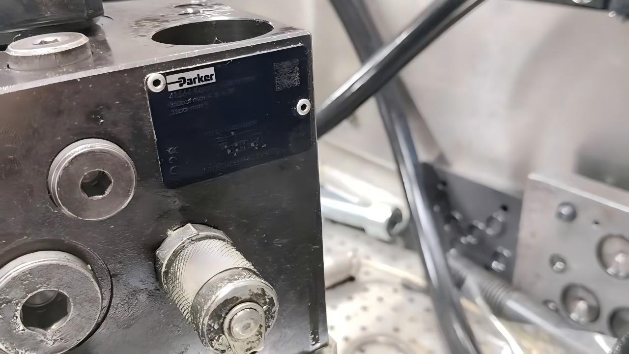
Parker TDP040E nameplate
1. Overview
This report documents a static null and gain check performed on a Parker TDP040E servo valve on our hydraulic test bench in September 2026. The check verifies two things before a valve leaves our workshop: that the electrical null (zero-command spool position) sits inside tolerance, and that the spool responds smoothly and repeatably as command current is stepped through its range. It is the baseline static characterization we run on every servo valve we service, and on a single-stage two-nozzle valve like the TDP040E it takes well under a minute.
The full check, from pressure ramp-up to the last command step, is captured in a 28-second video. The valve passed with a null bias of under 0.1 mA and clean, progressive response at every step.
2. Device Under Test
|
Item |
Value |
|
Manufacturer |
Parker Hannifin |
|
Model |
TDP040EH99C2NB0 |
|
Valve type |
Single-stage dual-nozzle servo valve |
|
Max. working pressure (A/B/X/Y) |
350 bar |
|
Max. drain pressure |
35 bar |
|
Country of origin |
Germany (Kaarst) |
|
Approvals |
CE |
The nameplate photo above was taken with the valve already bolted to the test manifold. The etched plate also carries a DataMatrix code and the Parker material identification line; the order record was checked against both before the test.
3. Test Equipment
|
Equipment |
Function |
|
Hydraulic test bench with stainless control panel |
Supply pressure generation, port pressure readout |
|
WIKA analog pressure gauges (0–250 bar) on A, B, P and X ports |
Visual confirmation of port pressures |
|
Panel-mounted digital indicators |
Supply pressure and flow display |
|
Fluke 189 multimeter, mA range |
Independent measurement of coil command current |
The bench supplies the command signal; the Fluke 189 was wired into the coil circuit as an independent check so the panel readout and a calibrated handheld meter could be compared at each step.
4. Test Conditions
|
Parameter |
Value |
|
Test type |
Static null bias and gain check |
|
Supply pressure P |
≈ 100 bar |
|
Work-port pressure at null |
Equal on A and B (no load, spool centered) |
|
Command current at null |
0 mA |
|
Command steps |
3.4 mA and 8.0 mA on the positive stroke |
A supply pressure of 100 bar is well above the point where null shift becomes visible on a valve of this size, and low enough that the check can be run without engaging the load circuit.

Parker TDP040E mounted on the test manifold
5. Test Procedure
- Verified the nameplate data against the order record, inspected the mounting face and O-rings, then torqued the valve to the manifold.
- Connected the coil plug to the bench harness and confirmed coil continuity before energizing anything.
- Ramped supply pressure to approximately 100 bar and confirmed A and B port gauges read equal pressure with the valve de-energized — the null condition.
- With zero command applied, measured the null bias current on the Fluke 189 in the coil circuit.
- Stepped the command current upward (3.4 mA, then 8.0 mA), watching the A/B pressure split develop on the panel gauges and confirming each step against the panel digital readout.
- Returned the command to zero and confirmed both port pressures converged back to the same value with no drift.
6. Results

Null bias measurement on the Fluke 189
|
Observation |
Result |
|
Null bias current |
-0.086 mA at zero command |
|
Panel current display at null |
-0.08 mA, matching the handheld meter |
|
Command step 1 |
3.398 mA |
|
Command step 2 |
7.99 mA |
|
Port pressure response |
Progressive A/B split at each step, no sticking |
|
Return to null |
Pressures converged, no drift observed |
|
Supply pressure |
≈ 95–100 bar throughout |
Three points worth noting:
- Null bias.-0.086 mA is a fraction of a percent of full-scale command current. A valve with worn torque motor clearances or contaminated nozzle flaps typically shows a null offset an order of magnitude larger, and it drifts as the oil warms. This one held steady through the whole check.
- Cross-check between meters.The panel display and the Fluke 189 agreed at -0.08 mA. The two independent current paths reading the same value means the bench’s own readout can be trusted for the gain steps that follow.
- Each command step produced an immediate, smooth pressure split between A and B. There was no hesitation or jump that would indicate a spool dragging on its bore — the failure mode we watch for on used valves.

Test bench panel during the check
7. Conclusion
The Parker TDP040EH99C2NB0 passed the static null and gain check. Null bias measured -0.086 mA at 100 bar supply, the panel and handheld meters agreed within display resolution, and the spool responded cleanly to command steps up to 8 mA with no sign of sticking or drift. The valve is in good working condition and ready for shipment or installation.
Video of the full check is available on our YouTube channel @FENGDUFF. For our other Parker valve test reports, see the blog archive.