

| Parameter | Specification Details / Code Meaning |
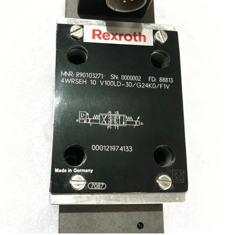
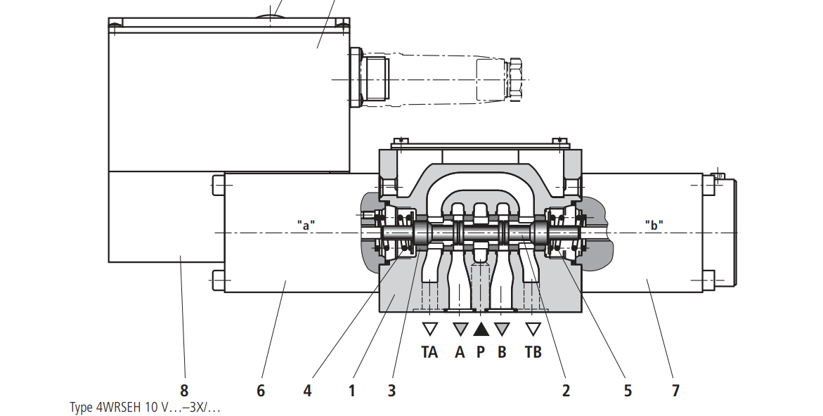
| Model Code | 4WRSEH 10 V100LD-30/G24K0/F1V |
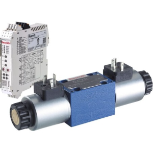
| Valve Type | 4WRSEH (High-response proportional directional valve, 2-stage, pilot-operated, with integrated electronics / OBE and electrical position feedback) |
| Nominal Size | Size 10 (NG10 / CETOP 05 / ISO 4401-05-04-0-05 mounting interface) |
| Spool Symbol | V (4/3-way servo spool characteristic with zero lap / critical overlap) |
| Nominal Flow Rate | 100 L/min (At a nominal reference pressure drop $\Delta p = 70\text{ bar}$ across the valve, or 35 bar per control edge) |
| Flow Curve | L (Linear flow characteristic curve) |
| Pilot Supply/Return | D (Internal pilot oil supply via port P, internal pilot oil return via port T) |
| Component Series | 30 (Series 3X: 30 to 39, designating structural and manufacturing design updates) |
| Supply Voltage | G24 ($+24\text{ V}$ Direct Current / DC) |
| Electrical Connection | K0 (Without mating plug; standard connector design for integrated electronics) |
| Command Value Input | F1 (Analog current command signal input: $4 \text{ to } 20\text{ mA}$) |
| Seal Material | V (FKM / Viton seals, highly compatible with synthetic fluids and mineral oils) |
| Max. Operating Pressure | 315 bar (At main ports P, A, B) |

📦 Warranty&Reture Policy:
🛡️ 1、One year warranty. If the product malfunctioned under proper usage per instructions manual within the warranty period, please contact us to obtain shipping instructions and send it back at your shipping costs.
🔍 2、14days evaluation and investigation takes placed after receiving yourreturn item.
❓ Frequently Asked Questions: Moog Proportional Valves
1. 🔍 Why is fluid cleanliness so critical, and what is the recommended standard?
First and foremost, Moog proportional and servo valves feature highly sensitive pilot stages, such as ServoJet® or nozzle-flapper systems, which operate with extremely tight tolerances. Consequently, even microscopic particulate contamination can jam spools, cause erratic control, or accelerate premature wear.
To prevent these issues, operators must maintain a fluid cleanliness level of ISO 4406 < 14/11 for an extended service life (or at least ISO 4406 < 16/13 for standard operations). In addition, you should always install a 10 $mu m$ absolute filter ($beta_{10} ge 75$) without a bypass line directly upstream from the valve inlet to catch harmful debris before it enters the system.
2. ⚡ What are the typical command signal options, and how do I prevent signal interference?
Generally speaking, modern Moog proportional valves (like the D661 series) utilize Integrated Electronics (OBE) and accept standard analog command signals, most commonly $pm$10 V or 4 to 20 mA. While voltage signals offer convenience for basic setups, current signals (4 to 20 mA) provide superior resistance to voltage drops and signal degradation during long-distance transmissions.
To ensure optimal performance, you must mitigate Electromagnetic Interference (EMI). Specifically, always use properly shielded cables and connect them correctly to the 6+PE electrical connector housing. Furthermore, keep all low-voltage signal wiring physically separated from high-voltage power lines to maintain absolute signal integrity.
3. 🛡️ What happens during a power failure, and how does the fail-safe logic work?
In the event of a sudden power loss or cable break, system safety becomes the top priority. Fortunately, Moog engineers built-in fail-safe centering logic layouts into these valves. Depending on your specific model configuration, internal spring forces or pilot pressure will automatically shift the valve spool to a predetermined safe position—such as a completely closed (neutral) position or a specific flow path.
Therefore, before initiating your very first system startup, you must verify the exact fail-safe code on your valve’s nameplate. By doing so, you ensure that your machinery’s emergency shut-down behavior aligns perfectly with your plant’s operational safety protocols.
Reviews
There are no reviews yet.