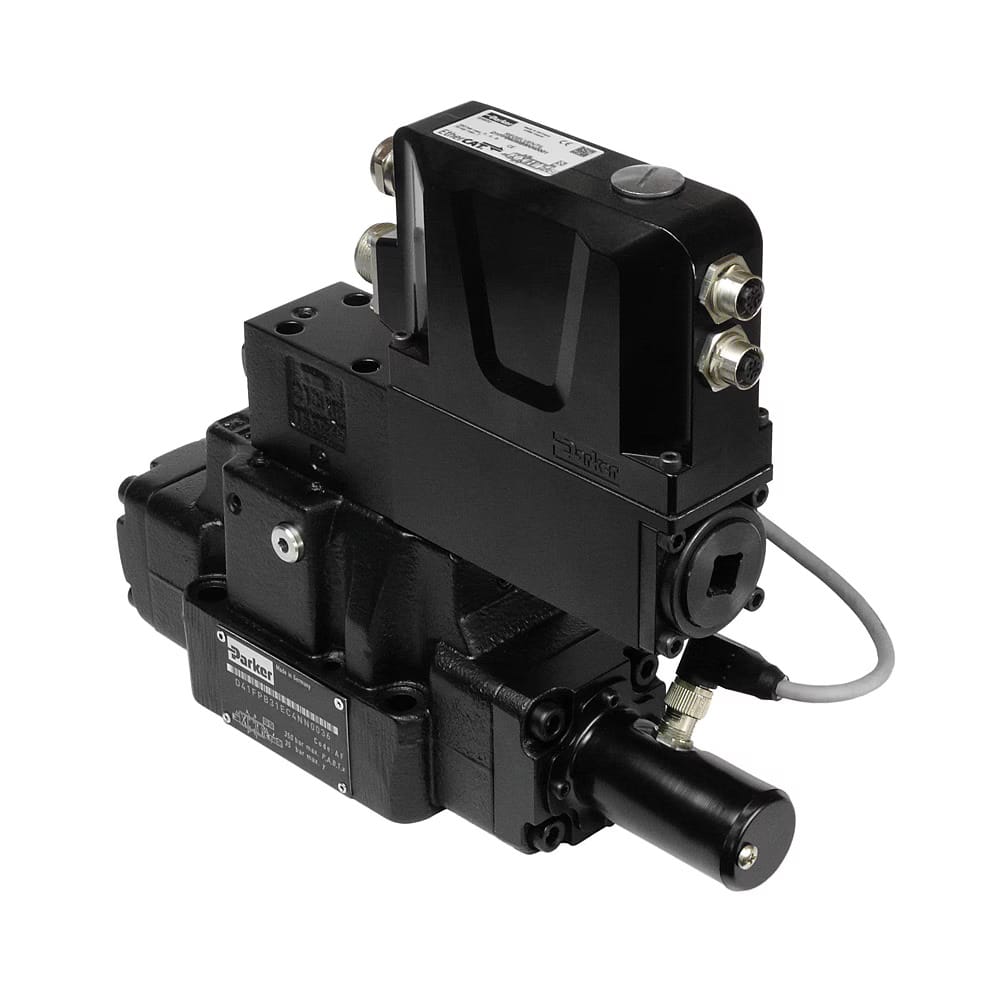


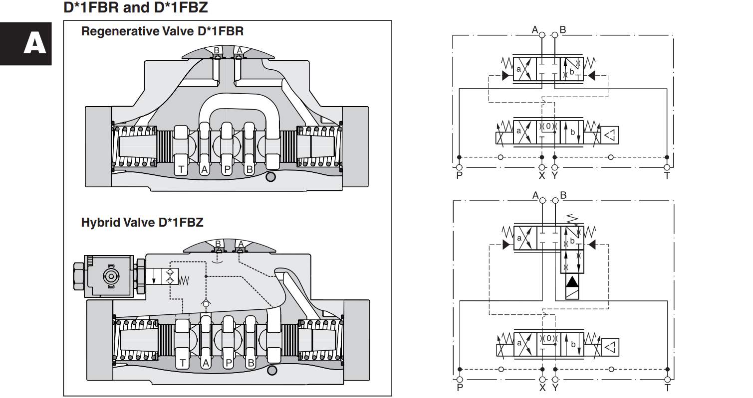
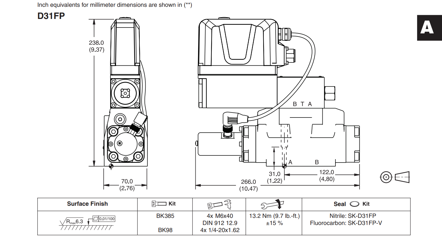
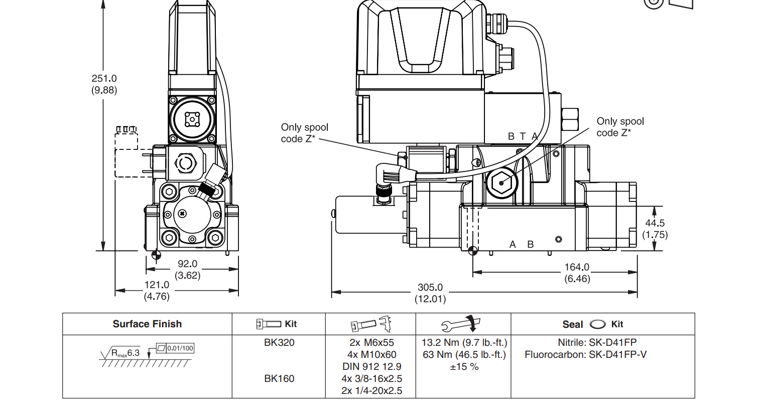
D41FP / D41FPE Series Parameter Specifications Servo Proportional Valve
| Category | Technical Parameter | Specification / Value | Unit / Standard |
| General / Mechanical | Valve Type | Pilot Operated Proportional Directional Valve | – |
| Actuation Type | Patented VCD® Actuator (Pilot) + Hydraulic (Main Stage) | – | |
| Size | NG16 / CETOP 07 / NFPA D07 | Standard | |
| Mounting Style | Subplate mounting (ISO 4401-07-07-0-05) | Standard | |
| Mounting Position | Unrestricted (Horizontal preferred) | – | |
| Weight | Approx. 8.9 | kg | |
| Hydraulic | Max. Operating Pressure (Ports P, A, B) | 350 (5075 PSI) | bar |
| Max. Operating Pressure (Port T) | 250 (3600 PSI) with external drain / 10 (145 PSI) internal | bar | |
| Fluid Type | Mineral oil according to DIN 51524…535 | – | |
| Fluid Temperature Range | -20 to +60 (-4 to +140) | °C (°F) | |
| Kinematic Viscosity Range | 20 to 400 (Recommended: 30 to 80) | cSt (mm²/s) | |
| Nominal Flow Rate | 100, 180, or 250 (at \Delta p = 5 bar per edge) | L/min | |
| Maximum Flow Rate | Up to 400 | L/min | |
| Fluid Cleanliness Class | 18 / 16 / 13 | ISO 4406 (1999) | |
| Static / Dynamic | Step Response Time (0 to 100%) | < 11 | ms |
| Performance | Hysteresis | < 0.1% | – |
| Sensitivity | < 0.05% | – | |
| Electrical | Duty Ratio | 100% ED | – |
| Enclosure Protection Class | IP65 (with correctly mounted connector) | EN 60529 | |
| Nominal Supply Voltage | 24 DC (Range: 22 to 30) | V | |
| Max. Current Consumption | 3.5 | A | |
| Command / Input Signals |
Code B: \pm10 V (Impedance: 100 k\Omega)
Code E: \pm20 mA (Impedance: < 250 \Omega)
Code S: 4 to 20 mA |
– | |
| Main Connection Options |
Code 0: 6 + PE (EN 175201-804)
Code 5: 11 + PE (EN 175201-804)
Code 7: 6 + PE + Enable
Optional: EtherCAT / Profinet fieldbus |
– |

📦 Warranty&Reture Policy:
🛡️ 1、One year warranty. If the product malfunctioned under proper usage per instructions manual within the warranty period, please contact us to obtain shipping instructions and send it back at your shipping costs.
🔍 2、14days evaluation and investigation takes placed after receiving your return item.
❓What Is a Proportional Valve?
A proportional valve is a hydraulic valve where a coil-driven solenoid pushes the spool directly in proportion to the input current.
🔍Key Characteristics:
- Higher flow than a servo valve
- Lower bandwidth
- ️ More tolerant of dirtier oil
Many include a position sensor (LVDT) on the spool, which closes the loop and turns the unit into a servoproportional. The valve shown here is a Bosch Rexroth 4WRPEH, one of the more common servoproportionals we see on the bench.
️🛡️A Solenoid-Driven Hydraulic Valve: Two Main Forms
Proportional valves come in two main forms: standard proportional (open-loop) and servoproportional (closed-loop with spool-position feedback). Most of what comes through the bench is one or the other, and the bench work overlaps but is not identical.
1️⃣ Standard Proportional (Open-Loop)
This is the simpler pattern. A pair of large coils on each end of the spool produces a magnetic force that pushes the spool against centering springs. The spool position is roughly proportional to the input current.
- Feedback: No internal position feedback; if the spool is fighting a load, the position can drift.
- Performance: Bandwidth is modest (often < 50 Hz), but flow capacity is higher than a servo valve and the tolerance for dirty oil is better.
- Common Models:
- Atos: DHZO, DKZOR (without transducer)
- Bosch Rexroth: 4WRA
- Yuken: EFBG
2️⃣ Servo valve proportional (Closed-Loop)
This type adds an LVDT (linear variable differential transformer) that measures actual spool position and feeds it back to onboard or external electronics. The drive electronics adjust coil current continuously to push the spool to the commanded position, even under load.
- Feedback: Continuous position feedback
- Performance: Bandwidth is higher than a standard proportional, deadband is smaller, and accuracy is better.
- Common Models:
- Atos: DLHZO, DLKZOR
- Bosch Rexroth: 4WRPH, 4WRPEH, 4WREE
- Yuken: EHFBG
- Duplomatic: DXE
⚡Shared Skeleton & Bench Work
Both types share the same core anatomy:
- A body bore with a spool inside
- Two solenoid coils on each end
- Centering springs
- Four hydraulic ports
- (On servoproportional variants) An LVDT and either an external driver card or onboard electronics (OBE)
Bench Work Note:
The differences are in the feedback loop and the accuracy of the spool fit. However, bench work overlaps a lot. A burned coil is a burned coil. A worn spool is a worn spool. The differences primarily show up in the LVDT and OBE channels on servoproportionals (which do not exist on the standard variants).


Reviews
There are no reviews yet.