Rexroth 0811404036 4WRPH 6 C3 B40L-20 Test Report & Video
Rexroth 4WRPH 6 C3 B40L-20/G24Z4/M (0811404036): Static Test of a Stock High-Response Valve, With Bench Video

The nameplate says it in four lines: MNR 0811404036, type 4WRPH 6 C3 B40L-20/G24Z4/M, FD 25015, serial 1202105235, Made in Germany. A size 6 high-response directional valve with spool position feedback and on-board electronics, fitted with the B40 flow element, the 40 L/min nominal class. The unit reached our bench as stock awaiting listing, so it went through the same incoming static session every valve gets here before we price it: a no-load flow sweep, then a leakage scan across null, both run at 10.00 MPa rated pressure and 10.00 V rated command. The inspection software printed its report, we photographed the pages, and we kept the walkaround video. This article reproduces the numbers exactly as printed, asterisks and all, and then says plainly what we make of them.
The Bench
Static work runs on the DT-B electro-hydraulic servo valve static tester; the dynamic tester cabinet in the same rack stayed dark through the session. The stainless gauge panel carries BLD test gauges, 0–60 MPa on the P and A channels, accuracy class 0.25. The P gauge’s serial, CE21100100, is legible in the video if you pause on the panel shot. Needle valves below the gauges trim each working chamber and the return line.
Command goes from the stand’s signal channel into the valve’s on-board electronics; flow and pressure come back through the acquisition channels, and the trace drawn live on the stand monitor during the sweep is the same trace the report screenshots are taken from. Nothing in this session was simulated or replayed: the curves in this article and the curves on the monitor in the video are one and the same recording.
No-Load Flow Characteristic
|
Item (as printed by the inspection software) |
Positive |
Negative |
|---|---|---|
|
Saturation flow (L/min) |
+231.70 * |
−222.95 * |
|
Saturation voltage (V) |
+6.94 * |
−5.72 * |
|
Flow gain ((L/min)/V) |
39.49 * |
47.02 * |
|
Linearity (%) |
−2.75 |
−2.01 |
Hysteresis: 2.23 % · Null bias: −0.57 % · Symmetry: 16.02 % *
The sweep drives the command out to roughly ±13.6 V, deliberately past the ±10 V rated window, so the flat tops on the curve are true mechanical saturation and not a clipped signal. That matters when you read the next section.
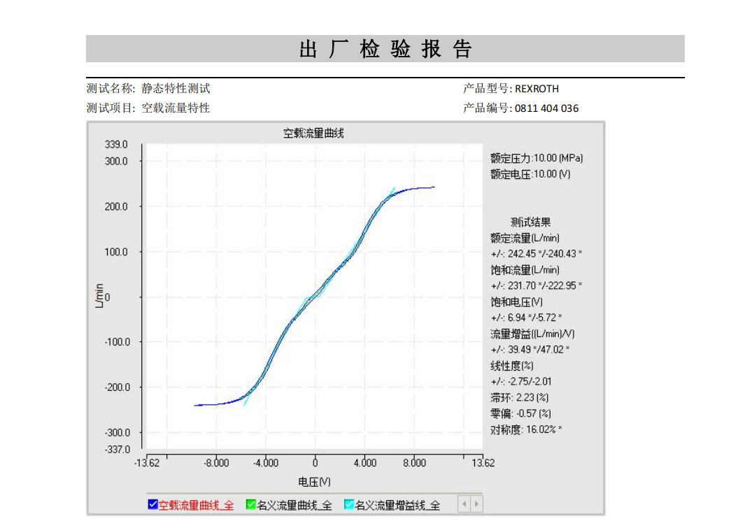
Three things in this table deserve a reading, and two of them are the asterisked lines people tend to either panic over or quietly delete. We do neither.
First, the saturation flow pair. Plus 231.70 and minus 222.95 L/min look absurd against a nameplate that says B40, until you remember what the bench is doing. With A and B open to tank and P held at 10 MPa, the entire supply differential sits across whichever metering land is open, and flow through a fixed orifice scales with the square root of that differential. The catalogue’s 40 L/min is quoted at the datasheet’s reference differential, a few bar across the land, not a hundred. Roughly six times the catalogue figure at 10 MPa is what an NG6 flow path passes when it stands wide open under full supply differential. It is not a mislabelled part. The asterisk is the inspection software marking the figure against the limit band it holds for the valve, and we keep it on the page rather than explain it away.
Second, the gain split. 39.49 (L/min)/V in one direction, 47.02 in the other, a 16 % directional difference, and that is precisely what the software’s symmetry line reports at 16.02 %. On a position-feedback valve the electronics close their own loop tightly, so a split of this size comes from the hydraulic side: the two metering notches are no longer twins. In service it means the controller meets a different plant gain in each direction. Open-loop speed control will never notice. A precision symmetric servo loop will, and the honest fix is per-direction gain scheduling in the controller, not a valve repair.
Third, the quiet lines. Linearity of −2.75 % and −2.01 % with a null bias of −0.57 % is unremarkable in the good sense, a minor electrical trim and done. Hysteresis of 2.23 % on the flow trace is wider than the electronics alone would produce on a position-feedback valve, so part of it is spool and sleeve friction. The curve itself is smooth and monotonic with no steps or flat spots away from null, which rules out the contamination damage we usually see as a kink in the trace.
Internal Leakage Characteristic
Zero-position internal leakage printed as 1.90 L/min at 10.00 MPa, asterisked like the flow figures.
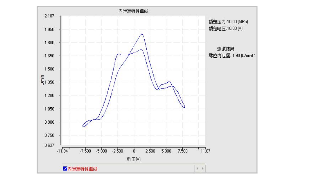
The trace behaves correctly. It sits around 0.85 to 0.9 L/min on the negative side of the sweep, climbs through null to its 1.90 L/min peak slightly to the positive side of electrical zero, steps down to a 1.2 to 1.35 L/min shelf, and tapers to about 1.05 L/min at the positive extreme. The shape is the part worth looking at: a sharp null peak with clean flanks is the signature of a lapped spool still doing its job, because at null both metering edges are partly open and the pilot flow has somewhere to go. Washed-out spools draw a broad flat hump instead of a peak, and this one draws a peak.
On our bench a freshly lapped size 6 spool typically stays under 1 L/min at this pressure. Read against that, 1.90 L/min is ordinary service wear: real, measurable, and nothing like end-of-life. The asterisk is the software telling you the figure sits outside the band loaded for a new valve. It is not telling you the valve is scrap.
Verdict
A usable valve with a documented personality. We cleared serial 1202105235 for open-loop duty and for moderate closed-loop duty. If your application demands symmetric response, budget for per-direction gain trim in the controller and accept roughly 2 % flow hysteresis; if it is a high-precision contouring axis, this is not the unit to pick, and saying so here is cheaper than saying it over the phone after delivery. The leakage figure is fine for continuous duty as long as the system’s cooling was sized for a couple of litres per minute at null, which a properly sized 10 MPa circuit absorbs without thinking. The full record leaves the bench with it: saturation flow +231.70 / −222.95 L/min at 10 MPa, reached inside +6.94 / −5.72 V of command, flow gain 39.49 / 47.02 (L/min)/V, linearity −2.75 / −2.01 %, hysteresis 2.23 %, null bias −0.57 %, symmetry 16.02 %, zero-position internal leakage 1.90 L/min. The asterisks stay in the tables above because they belong to the record, and a record you have edited is not a record. Buy this valve for what its curves say, not for what a catalogue page promises.
The Test Video
The recording runs 29 seconds and is unspectacular on purpose. It opens on the nameplate, moves to the P and A test gauges, pans across the tester cabinets and the pushbutton panel, and ends on the stand monitor mid-sweep with the flow trace still drawing. A few frames carry motion blur from the pan; the nameplate photograph at the top of this article is the clean record of the unit’s identity.
Video: Rexroth 4WRPH 6 C3 B40L-20/G24Z4/M static test, bench walkaround
Model reference: Rexroth proportional and servo valves in stock · Manufacturer product page for MNR 0811404036: Bosch Rexroth · Earlier report in this series: Rexroth 4WRTE 16 V200L-43/6EG24K31/A5M static characteristic test
About the Tester
Marginal Hydraulic keeps this bench in-house in Guangzhou because we sell and refurbish what we test. Every servo, proportional and cartridge valve that crosses the plate, Moog, Parker, Rexroth, Vickers and equivalents, leaves with a static record: no-load flow, null leakage, and, where the job calls for it, pressure cycling up to 350 bar. Questions about this unit’s data or its availability: duffeng@marginal-hyd.com.
2026.09.14